Efficient data acquisition and reconstruction for air-coupled ultrasonic robotic NDE
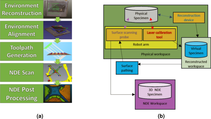
A new framework for conducting autonomous scanning on complex parts from surface scanning NDE techniques is proposed. The first process of this framework starts with the initial environment reconstruction. This is followed by localizing the robot by registration of the environment to the scanning workspace. The next step is toolpath generation, in which a novel method is proposed: ray-triangle intersection arrays.
This process involves projecting rays onto the initial mesh and checking for intersections, resulting in a zig-zag pattern of “waypoints” holding position and tilt information for the probe on the toolpath. This provides robust scan profiles for any input mesh, albeit with smoothing limitations with respect to tool movements compared to b-splines. Figure 1 illustrates the considered framework depicting the reconstruction-to-NDE scanning process. Following path computation, the generated path is transmitted to the robot, initiating the NDE scanning process. The NDE scan synchronizes the recorded position of the robot’s end effector with the NDE data, generating NDE point data within 3D space respective to the robot’s workspace. This resultant data undergoes post-processing, involving actions such as removing trend effects or converting the 3D NDE point data into a mesh.
Geometric point cloud from physical environment
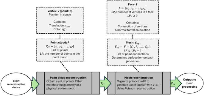
The goal of this section is to define an output to a cyber environment \(E_{cy}\) based on a physical environment that will be used for path planning. Starting with the basics, the raw output from a reconstruction device is a point cloud labeled as a set of points P. This process is known as point cloud reconstruction. Eventually, P needs conversion into a mesh, forming the reconstructed environment \(E_{cy}\). A point cloud P contains a local set of points with indices \(p_i\), holding vertex information \(t_{xyz}\) and color information rgb. Therefore, \(p_i = [t_{xyz_i}, rgb_i]\), and \(P = [p_1, p_2, p_3, \ldots , p_{LP}]\), where LP is the number or “length” of points in the point cloud. Point clouds are obtained by an “observer,” which in this case would be the reconstruction device of choice.
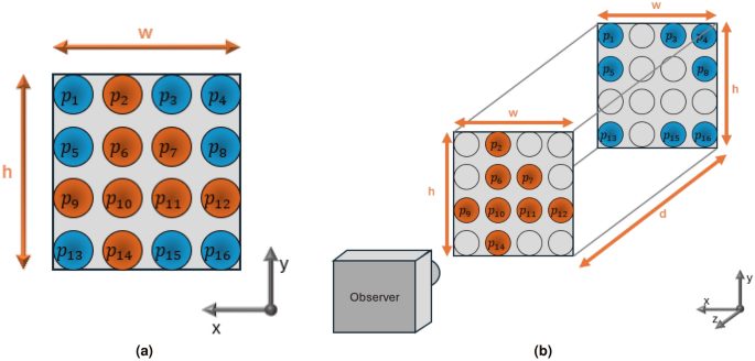
From point clouds obtained from stereo cameras, the points are typically organized in a grid-like fashion along local coordinates x and y, with variations along z to represent depth. However, the output is unraveled into a 1D vector form. For example, if a stereo camera has a resolution of 1920\(\times\)1080 points, then LP = 2073600 in the 1D vector \(P_{cy}\). Each point falls within width w and height h boundaries local to the point cloud’s frame, creating a grid-like formation of points. Parameters w and h depend on the camera’s field of view and the distance between a physical component inside the workspace. An example is shown in Fig. 2. In this example, a 4 \(\times\) 4 grid-like point-cloud is shown, with dimensions \(w \times h \times d\) for width, height, and depth. From the point cloud definition, \(P_{cy} = [p_1, p_2, p_3 \ldots , p_{16}]\) with LP = 16 and the orange points are closer to the observer than the blue points. The clear points are just placeholders to show orthogonality between the depths, as in, the arrays will hold the same x and y positions with depth. From a reconstruction device, the depth of these points should move along the surface geometry of the environment to reconstruct along the grid. Points that are not visible to the device are defined as p = null and are not considered in the output reconstructed point cloud \(P_{cy}\).
Mesh generation from point cloud
From the point cloud generated, a mesh is generated by connecting vertices together. This process is known as mesh reconstruction. This will obtain a list of faces that will define the surface profile of the physical environment within virtual space. Covered are the basic principles of faces generated from reconstruction and its relation to path planning, with a breakdown shown in Fig. 4. Two popular algorithms are Poisson reconstruction29,30 and Delaunay triangulation31.
A mesh comprises a set of faces F with face indices fi, where \(F = [f_1, f_2, \ldots , f_{LF}]\), and LF is the number of faces. Faces are constructed from vertices, with \(f_i = [p_1, p_2, \cdots , p_{LP_F}]\), where \(LP_F\) is the number of vertices in a face with \(LP_F \ge 3\) and \(LP_F \ge LF+2\) assuming \(LF \ge 1\). Vertices function as the foundation of meshes and are defined from P through reconstruction. An example of faces defined by vertices is shown in Fig. 3. The vertex list V differs subtly from P since reconstruction may reorganize V. Mesh processing may further reorganize V. Although the organization of faces through vertex indexing is abstracted, it is mentioned for contextual purposes. Output data sets typically use this organization to significantly reduce the redundancy of overstated vertices.
Example showing face formations from vertices, oriented to the reader with \(LP=4\). The properties of each formation is shown in Table 1.
Faces are essential in the ray-triangle intersection array algorithm later discussed. Faces contain a flat area between its vertices. A point of intersection will lay on this area, determining probe positioning. Faces also contain a single normal throughout their area, determining probe tilt. A normal from a triangular face, or \(LP_F= 3\), may be calculated from the following equation: \(n_f = \frac{c}{||c||}\), with \(c = v_a v_b \times v_a v_c\) for a face \(f = [v_a, v_b, v_c]\). Faces may be triangulated using face culling algorithms32.
The order of vertices defined by a face is important for normal orientation. The position of vertices per face determines facial orientation, including the normal or the direction the face is pointing towards. For example, \(f=[v_a,v_b,v_c]\) in a counterclockwise formation will face the normal in a positive orientation, while \(f=[v_a, v_c, v_b]\) in a clockwise formation will flip the normal in the negative direction. In other words, an incorrect vertex order will flip the probe in the opposite direction, inevitably leading to a collision between the probe and sample!
Scanning environment post-processing
Post-processing on the mesh is recommended for effective path planning. Cropping out background components is recommended to prevent manipulation in areas outside the scanning region. This step may also aid in eliminating curved beveling on edges of a sample that merges with background components, a common occurrence during reconstruction. Additionally, smoothing the scan surface is recommended to avoid issues with coarse surfaces that might lead to overcompensation in the rotation of the actuation system. While this article does not delve into the optimization and automation of post-processing procedures, techniques such as manual face cropping, face simplification or decimation, and Laplacian smoothing33 are commonly employed to enhance path planning and scanning results.
Background removal
In a workspace, two classifications of physical objects are considered within a point cloud snapshot: the sample to reconstruct and the background. The toolpath generation algorithm aims to retain only the sample under test, excluding other components. It is crucial to identify what qualifies as background in the workspace. This may include holders like vices, which may appear attached to the sample and need removal. If the sample is on a table, the table itself is considered part of the background. Components outside the robot’s workspace might also appear in the snapshot as background, including the robot and any related wires to the NDE probe. It is essential to note that background components may be important for collision detection. Thus, it is recommended to keep one mesh with the necessary background for collision detection and another for path planning.
To eliminate backgrounds, two methods were employed: manual removal and statistical outlier removal. Statistical outlier removal was a default technique applied to stray point clouds to prevent them from affecting the mesh reconstruction process. Manual cropping was also employed, typically if a background component, such as vices or tables, merged with the sample. For future works, an autonomous solution for background removal will be considered.
