Functional soft robotic composites based on organic photovoltaic and dielectric elastomer actuator

The main functionalities of OPV-DEA are simultaneous voltage-controllable actuation and energy harvesting. To realize this concept, we laminated an OPV, a DEA, and other substrates sequentially using a layer-by-layer process. Moreover, we employed dielectric elastomer minimum energy structures (DEMESs), which is a configuration of DEA15,16. This configuration enables the generation of out-of-plane deformations by attaching a pre-stretched DEA onto a flexible substrate and it has been applied to various robots, such as a gripper17, crawling robot18, and fish robot19. Figures 1a and b illustrate the structure of OPV-DEA and Fig. 1c shows the fabricated OPV-DEA. As shown in the image, an OPV is placed on the top of a pre-stretched DEA, which is attached to a flexible substrate. Because the OPV is attached to the DEA in a flat state, wrinkles were formed in the OPV in the initial bending state (i.e., zero actuation voltage). These wrinkles enabled its bending deformation despite its inextensibility. Owing to the DEMES configuration, when a voltage was applied to the DEA, the entire structure exhibited a bending motion toward the flat shape. This bending motion enabled the integration of OPV-DEA with a soft robot capable of moving on the surface of water, where OPV enhanced its run time by harvesting energy from the surrounding environment (Fig. 1d).
To integrate OPV and DEA, there are several design factors, such as geometry, actuator configuration, and terminal accessibility, which should be considered. This integration should be capable of providing a mechanical output without obstructing the energy harvesting capability and vice versa. Thus, in this study, we selected a simple and straight design for the OPV-DEA with a main rectangular frame of 28 mm × 51 mm (width × length; Fig. 2). For the DEA part, a squared active area (area in which electrodes are overlapped) of 20 mm × 20 mm was employed, and this was located at the top center of the device, while the two terminals were designed to pass through both edges to avoid any electrical short circuit due to high voltages (Fig. 2a). The determined outline dimension of OPV was 24 mm × 24 mm (Fig. 2b). The effective area of the OPV consisting of the indium tin oxide (ITO) and silver (Ag) layers, which was located at the center of the DEA’s active area, was 10 mm × 10 mm. The terminals of OPV are designed such that they were located at the center to avoid any short circuit and electrical breakdown against the DEA part.
The fabrication of OPV-DEA, which is summarized in Fig. 3, mainly involves the lamination of the DEA and OPV, beginning from the formation of the DEA part. An 0.5 nm-thick acrylic dielectric elastomer membrane (VHB 4905, 3 M) with initial outline dimensions of 31.8 mm (length) × 31.8 mm (width) was pre-stretched to a ratio of 1.6 and held between two acrylic supports (Fig. 3i-ii). Compliant electrodes made of a conductive acrylic elastomer (thickness = 33 µm; ARcare 90,366, Adhesives Research) were attached to both sides of the elastomer, after which a 125 µm-thick polyimide (PI) film was placed on the elastomer as the flexible substrate ((Fig. 3iii-v), forming the DEA part. The adhesive nature of the acrylic elastomers enabled the lamination of the layers without the need of additional glue and enabled rapid fabrication. In the previously-described steps, both the dielectric and conductive elastomers were cut using a laser machine (Speedy 300, Trotec), whereas the PI film was cut manually using a cutter knife. Thereafter, an OPV prepared on a glass plate was placed on top of the DEA. Subsequently, the glass plate was removed carefully using a plastic tool (Fig. 3vi-vii). Lastly, using a pair of scissors, the entire assembly was released, and all the unnecessary parts were cut, resulting in a final OPV-DEA with an initial bending angle (Fig. 3viii-ix). Further details on the fabrication process of the OPV part can be found in the Method Section.
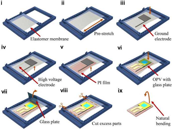
Fabrication process of OPV-DEA. (i) Elastomer membrane is fixed to the acrylic bracket. (ii) With the aid of the acrylic bracket, the membrane was prestretched. (iii) Ground electrode was attached to the membrane. (iv) High voltage electrode was attached to the other side of the membrane. (v) Pre-cut polyimide (PI) film substrate is attached to the bottom of the assembly. (vi) OPV with the glass plate is attached to the top of the assembly. (vii) Glass plate is removed from the assembly. (viii) The excess parts is cut using a pair of scissors. (ix) the final OPV-DEA is obtained.
The OPV-DEA offers multifunctionality, serving as an energy harvester and actuator. The OPV part harvests energy from external lights, providing a renewable power source. Conversely, the DEA part allows for voltage-controllable actuation. To elucidate the characteristics of these functionalities, we characterized the OPV-DEA across several performance metrics.
The evaluation of the actuation functionality involves assessing the actuated bending angle and blocked force regarding the applied voltage. Figure 4a depicts the measured data, indicating that the actuated angle increases with voltage, reaching a peak value of 15.6° at 9 kV (Supplementary Video S1). The actuated force plotted in Fig. 4b exhibited a correlation with voltage, rising to a value of 1.6 mN at 9 kV. This value is within the same order of magnitude as forces observed for other DEA-based actuators of similar type (i.e., DEMESs) reported in the literature15,16,17.
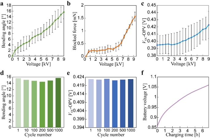
Characterization results of the OPV-DEA. (a) Bending angle as a function of the applied voltage. (b) Blocked force as a function of the applied voltage. (c) The open circuit voltage (VOC) of the OPV as a function of the applied voltage. Data in (a)–(c) are the average of four samples. (d) Bending angle under cyclic actuation (0 and 9 kV). (e) The VOC values of the OPV under cyclic actuation (0 and 9 kV). (f) Battery voltage as a function of the charging time.
To evaluate the energy harvesting functionality, we initially assessed the electrical characteristics of a non-actuated OPV-DEA, including output voltage and current, fill factor (FF), and power conversion efficiency (PCE). The device demonstrated an open-circuit voltage (VOC) of 0.395 V, a short-circuit current (ISC) of 5.8 mA, and an FF of 55.5%, resulting in a power output of 1.35 mW and PCE of 11.4%, under an incident power irradiance of 11.7 mW/cm2. These results are consistent with those from other similarly structured stand-alone OPVs reported in the literature7. The interaction between the OPV part and DEA part is pivotal for OPV-DEA functionality. Since the active and effective areas of the DEA and OPV parts are located in the region of the device, respectively, the effective area of the OPV part is anticipated to unfold when the device is actuated towards the flat state (Fig. 1a). This may result in an increase in harvested energy as the overall effective area expands with the flattening of the device. To investigate this behavior, we proceeded to characterize the open-circuit voltage VOC of the OPV-DEA under voltage-controlled deformation and an incident power irradiance of 11.7 mW/cm2. As shown in Fig. 4c, as the applied voltage for the DEA part increases, the device gradually flattens, resulting in a subsequent rise in the measured VOC value. The device exhibited an initial value of 0.395 V, reaching a peak of 0.423 V, reflecting a total increase of 28 mV. This finding indicates that the relationship between the OPV part and DEA part can be beneficial and does not impede OPV-DEA operation.
Given that the OPV-DEA is comprised of several film materials laminated together, it is crucial to assess its reliability. Therefore, we examined its actuation and energy harvesting performance through repeated cycles of up to 1,000. The energy harvesting performance was measured via VOC, while the actuation performance was determined through the bending angle. The result consistently showed stable outputs throughout the tested actuation cycles (Fig. 4d,e). Significantly, the changes in actuation and energy harvesting performance during the cycles were marginal, registering only 5.1 and 0.21%, respectively. This underscores the high robustness of OPV-DEA, making it well suited for soft robotic applications that often involve cyclic action.
To demonstrate the applicability of the OPV-DEAs in soft robotics, we integrated them into an untethered swimming robot (Fig. 5a). The robot is self-contained, comprising two OPV-DEAs connected to elastic fins made of a laser-cut PI film, a high-voltage DC/DC converter (AH60P-5, XP power), circuit board, microcontroller (AtTiny85), main battery (LiPo 3.7 V, 110 mA), and an auxiliary battery (NiMH 1.2 V). The robotic system consists of two main modules: a locomotion module and an energy-harvesting module. The former facilitates the bending actuation of the OPV-DEAs, which in turn drives the oscillation of the fins, generating thrust forces that propel the robot forward (Fig. 5b). The latter module harvests energy from external lights to charge the auxiliary battery, which powers the microcontroller.
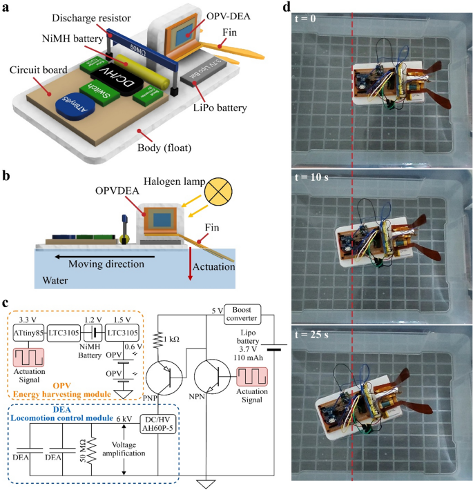
Swimming robot based on the fabricated OPV-DEA. (a) Structure of the robot. It employs two OPV-DEAs, which are connected to an elastic fin made of PI film. (b) Working principle of the robot: the energy of the external light (halogen lamp) gets absorbed by the OPV-DEAs and is then utilized to drive the actuators, pushing the fin downwards and propelling the robot forward. (c) Electrical circuit diagram of the robot system, which is divided into two modules responsible for locomotion and energy harvesting. (d) Sequence of the swimming of the robot.
Figure 5c shows that the main power source for the energy-harvesting module consists of two OPVs arranged in series within the OPV-DEAs. This array registered a Voc of 0.66 V, a short-circuit current (\({I}_{SC}\)) of 5.7 mA, and FF of 40.0%. Consequently, it provided a power output of 1.5 mW and a PCE of 13.5% when exposed to an incident power irradiance of 11.7 mW/cm2. To charge the auxiliary battery (NiMH 1.2 V) effectively, the power output was boosted by incorporating a boost converter circuit (LTC3105). This circuit is specifically designed to work with small solar cells, effectively increasing the voltage to 1.5 V.
We performed a charging test with the robot in a non-actuated state, observing an initial charging current of 91 µA. The voltage steadily increased, raising the battery level from 0.85 V to a final level of 1.05 V under an incident power irradiance of 11.7 mW/cm2 (Fig. 4f and Supplementary Video S1). The microcontroller (ATtiny85) in the energy-harvesting module controlled the operations of the robot. However, this microcontroller requires a minimum operation voltage of 3.3 V. To elevate the output voltage of the OPV-charged auxiliary battery to the necessary level, we connected another booster circuit (LTC3105) between the microcontroller and auxiliary battery (Fig. 5c). Upon activation, the microcontroller produces a square signal to actuate the OPV-DEAs. The locomotion module is powered by the main battery (LiPo battery 3.7 V, 110 mA), which was previously charged using a DC power supply (RD6018, Riden). Figure 5c shows that the main battery was connected to a miniaturized high-voltage DC-DC converter (AH60P-5, XP power) that elevates the output up to 6 kV.
The experiment conducted in a water tank revealed that the swimming speed of the robot was 21.7 mm/s when operated at 6 kV with a driving frequency of 2.5 Hz (Fig. 5d and Supplementary Video S1). This experiment was performed using the energy harvested and stored in the auxiliary battery from the previous test. The high-voltage DC-DC converter dominates the overall power consumption of the robot, which is approximately 1.5 W. This value is significantly higher than the output of the on-board OPVs (1.5 mW). Consequently, the DEAs in the robot cannot be directly powered by the OPVs. Instead, they were used to charge the auxiliary battery that powers the controller. This setup underscores the utility of OPVs. Without a signal from the controller, which is powered and operated by the OPVs, the robot would be incapable of executing any controlled movements. Furthermore, the OPVs supplying energy to the controller improve the efficiency of the robot. A longer operation time for the controller ensures the standby time of the robot, which is often crucial for tasks such as remote communication and fixed-point observation during missions. Therefore, the observed swimming locomotion of the robot illustrates the versatility of OPV-DEA, serving as both an energy harvester for the power and a voltage-controllable actuator for robot locomotion. This demonstrates its practical applicability in soft robotic systems.


